
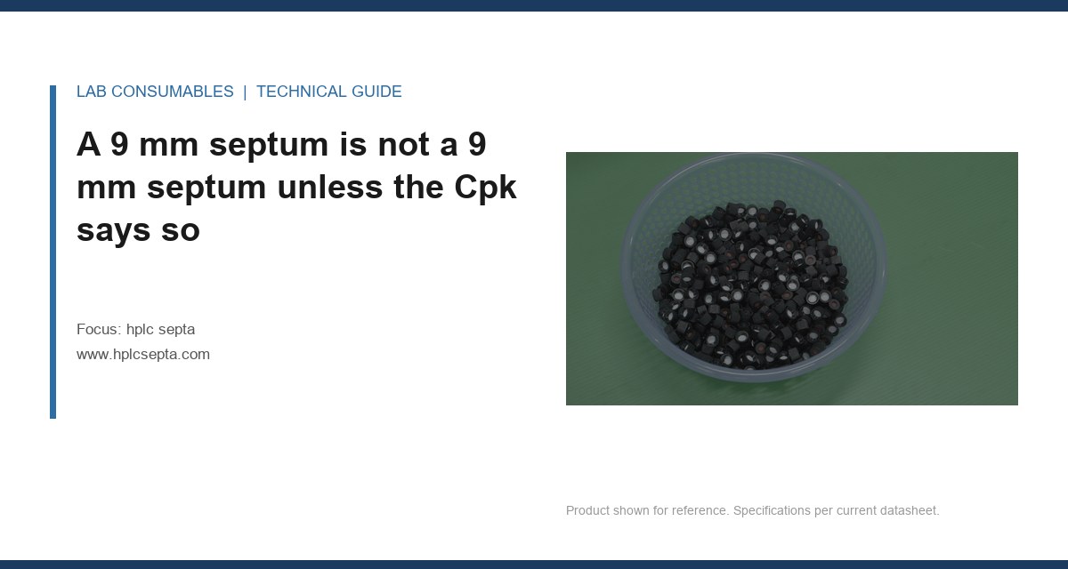
A lot of 50,000 PTFE/silicone septa came back last March because the diameter drifted 0.06 mm over the mold’s seventh cavity. That is less than a human hair, and it was enough to make the closures snap on hard and leak solvent vapor at 45°C. The QC instruments caught it only after a customer returned vials for cap pop-off. I keep that lot tag pinned in my office. It is the reason we now measure hplc septa dimensional tolerance capability as a process number, not a drawing exercise.
The drawing says 9.00 mm ±0.10 mm for the silicone body. That is the easy part. What matters is whether the molding or cutting process can hold that band week after week, across eight cavities, at 200°C, after the PTFE layer bonds. Process capability uses two numbers: Cp, which compares the tolerance band to the process spread, and Cpk, which also accounts for how centered your mean sits. A Cp of 1.33 sounds fine, but if the mean has drifted 0.04 mm upward, the Cpk drops to 0.88. That is a process producing scrap on one tail. We require a Cpk of 1.33 minimum on septum diameter before a mold goes into production, and we do not accept the tool until the worst cavity meets that, not the average of all eight.
The math is simple. For a 9.00 ±0.10 mm septum, the total tolerance is 0.20 mm. A Cpk of 1.33 means the process spread, expressed as six standard deviations, fits inside 0.15 mm, and the mean sits at least 0.0625 mm from the nearest limit. In practice, that means a real standard deviation under 0.025 mm. Most die-cut and compression-molded septa sit at a sigma of 0.03 to 0.05 mm on diameter. They pass the print but fail capability. That is why two suppliers with identical spec sheets send you different seals. One holds 0.02 mm sigma, the other lives at 0.045 mm. The Cpk number is the difference that shows up in cap fit and puncture behavior, and it does not appear on the certificate of analysis.
Process limits: what each manufacturing method can actually hold
There are three common ways to make HPLC septa: die cutting from pre-laminated sheet, compression molding, and injection molding with liquid silicone rubber, or LSR. Each one has a different tolerance floor. If you specify tighter than the process can hold, you get two results: high scrap, or a supplier who cherry-picks parts and ships you the bell curve’s leftovers. I have seen both. Let me put numbers to each method.
Die-cut PTFE/silicone laminate
Die cutting runs a flat sheet of laminated PTFE and silicone through a steel rule or matched metal die. Diameter tolerance on a well-maintained die is ±0.05 mm to ±0.08 mm. Thickness is controlled by the incoming laminate, usually ±0.10 mm on total thickness and ±0.025 mm on the PTFE face layer. The hidden problem is edge quality. A dull die pulls silicone, leaves a ragged edge, and can smush the PTFE layer thinner at the cut line. We replace steel rule dies every 100,000 to 150,000 strikes, depending on durometer. The die’s corner wear also creates a taper across the septum: the side facing the punch can be 0.03 mm smaller than the side facing the base plate. That diameter taper is what causes septa to wedge into caps at an angle.
Die cutting is the cheapest process and the least capable for tight diameters. If you need ±0.05 mm or better across a million septa, do not start with die cutting. Most die-cut septa I have measured run Cp values between 0.80 and 1.10 on diameter, meaning they fail a 1.33 requirement even though they hit the print. For general-purpose HPLC use at injection counts under 50, that is usually acceptable. For autosampler caps that seat in a hard polypropylene ring, it is not.
Compression molded PTFE-bonded silicone
Compression molding places a pre-cut silicone preform into a heated cavity, lays the PTFE face on top, and closes the mold. Diameter tolerance runs ±0.08 mm to ±0.12 mm on a well-conditioned tool, with thickness at ±0.05 mm. The advantage is in the bond. Because the silicone cures against the PTFE under heat and pressure, you get a true adhesive-like polymer interlock. The weakness is flash. Compression molding always produces flash at the parting line, usually 0.05 mm to 0.15 mm wide. That flash must be cryogenically deflashed or hand-trimmed. If it is not, the septum’s effective diameter at the cap seating surface changes, even though a caliper across the center says it is in tolerance.
The bigger issue is cavity-to-cavity variation. A 16-cavity compression tool will not fill identically cavity to cavity. The center cavities run hotter and fill denser; the edge cavities run cooler and produce slightly smaller parts because the silicone preform does not flow to the same extent. I have measured 0.07 mm diameter spread across a 16-cavity tool running steady-state. That is why our production QC samples each cavity separately, and why the Cpk is calculated per cavity, not pooled. A pooled sample hides the worst cavity. That is exactly how we got the lot I mentioned at the start. The seventh cavity produced parts at 9.03 mm mean. The pooled average stayed under 9.02. Everyone in the room saw a passing number while one cavity shipped drifts.
LSR injection molded silicone with PTFE overmold
Liquid silicone rubber injection molding is the tightest method. The LSR enters a closed mold as a two-part liquid, cures in 30 to 90 seconds, and can be overmolded onto a preformed PTFE disc. Diameter tolerance with a well-designed cold-runner tool is ±0.03 mm to ±0.05 mm, sometimes better on a single-cavity tool. Thickness holds ±0.03 mm. The reason is mold fill: LSR flows at lower viscosity than a compression preform, so cavity pressure is more uniform. You can push Cp values of 1.67 or higher on a mature LSR process.
The cost is tooling and cycle time. An eight-cavity LSR mold for 9 mm septa costs more than a compression tool by a factor of two to three. Cycle time is shorter than compression molding, but the initial capital is brutal for low-volume products. LSR also carries a specific failure: the PTFE disc can shift during mold close, causing off-center face placement. That is a concentricity problem, discussed below, and it is more common in LSR overmolding than in compression bonding.
| Process | Typical diameter tolerance | Typical thickness tolerance | Realistic Cpk on diameter | Main failure mode dimensionally |
|---|---|---|---|---|
| Die-cut laminate | ±0.05 to ±0.08 mm | ±0.10 mm total / ±0.025 mm PTFE | 0.80 to 1.10 | Edge taper and dull-die diameter creep |
| Compression molded | ±0.08 to ±0.12 mm | ±0.05 mm | 0.90 to 1.30 per cavity | Flash and cavity-to-cavity spread |
| LSR injection molded | ±0.03 to ±0.05 mm | ±0.03 mm | 1.33 to 1.67+ | PTFE face eccentricity |
This table is why I ask a supplier one question before looking at their catalog: what process are you molding these on? The answer determines whether their printed tolerance means anything. A supplier quoting ±0.03 mm on a compression-molded part is either lying or sorting 100% with an optical sorter. Sorting works, but you pay for the scrap in the per-unit price, and you still have to trust that their sort threshold matches your incoming inspection method.
Concentricity and the PTFE face: the two dimensions nobody measures until failure
Diameter, thickness, and hardness show up on supplier datasheets. Two dimensions do not, and they drive more field failures than any of the listed ones. The first is concentricity of the PTFE face relative to the silicone body. The second is PTFE face thickness uniformity from edge to center.
PTFE face concentricity
The PTFE face is the needle entry surface. If it sits 0.15 mm off center on a 9 mm body, the needle can strike the edge of the PTFE layer or slip past it into bare silicone. Bare silicone punctures differently. It drags, cores, and can push debris into the vial. The concentricity requirement depends on the needle gauge and target diameter, but for a 9 mm septum with a 1.5 mm target zone, I hold PTFE face placement to within 0.10 mm of true center. That means measuring the offset as a radial runout, not a diameter. The drawing rarely calls it out. The process has to control it anyway.
Concentricity is hard to measure with a caliper. We use an optical comparator or a vision system at 20x, lighting the part from below so the PTFE edge shows as a dark ring against the translucent silicone. On a good process, the worst-case offset across a 1,000-piece sample is under 0.06 mm. On a bad LSR overmold process, offset can run 0.12 mm or more, frequently on one cavity where the PTFE disc sits loose in the mold before close. That is a cavity-specific defect. You cannot detect it by looking at the mean offset of the whole run; you need a per-cavity histogram.
PTFE face thickness uniformity
PTFE face layers come in nominal thicknesses: 0.05 mm, 0.10 mm, 0.20 mm, 0.25 mm. The common HPLC spec is 0.10 mm or 0.20 mm. The face does one hard job: it resists coring and provides a slick, inert puncture surface. If the face is 0.20 mm in the center but 0.12 mm at the edge, two things happen. The needle hits a thin spot if it enters off-axis, and the silicone swells upward through the compressed thin regions after repeated punctures. I have seen this in a lot where the PTFE disc had been punched with a dull die from the same sheet direction for too long. The punch deformed the PTFE into a slight dome before lamination. The lamination press flattened it visually, but the residual stress left a center-thin profile. Average face thickness across the septum read 0.18 mm. The center measured 0.11 mm. That is not a spec failure on average; it is a functional failure at the puncture point.
We specify PTFE face thickness as average thickness ±0.02 mm and center-to-edge difference under 0.03 mm for 0.20 mm face stock. That center-to-edge requirement is the one that catches dome-shaped and edge-loaded faces. It is measured with a drop indicator on a surface plate, three points per septum: center, mid-radius, and 0.5 mm from the edge. The difference between center and edge is the number that goes on the certificate.
Flash, parting line, and the dimensions that change after molding
Dimensions are not frozen at the mold. Three post-mold effects shift them, and a good tolerance capability study accounts for all three.
Flash removal. Compression-molded septa always have flash. Cryogenic deflashing at minus 100°C or below removes it, but it also shrinks the silicone body by 0.01 to 0.03 mm on diameter and can leave a slightly frosted edge. Hand-trimming is worse: operator pressure cuts a flat on one side of the part, turning a 9.00 mm round into a 8.96 mm oval with a flat. We deflash cryogenically and then run an optical sort for out-of-roundness. The pass criterion is out-of-round under 0.03 mm on diameter.
Compression set. Silicone under sustained load in a closed cap takes a set. A septum sitting in a pre-crimped cap for six months can lose 0.02 to 0.05 mm of uncompressed thickness. That is not a defect; it is a material property. The dimension that matters is the recovered thickness after 30 minutes at 70°C, per ASTM D395 Method B. For 50 Shore A silicone used in septa, compression set should stay under 20%. Higher set means the septum does not rebound after the needle withdraws, and you get a slow leak path around the puncture. We see compression set drift when the silicone cure time is cut short. Undercured silicone has good immediate thickness readings but fails the 70°C set test by 5 to 8 points.
Post-cure shrinkage. LSR parts shrink after molding as volatiles off-gas. An LSR septum measured 30 minutes out of the tool will read 0.02 to 0.04 mm larger than one measured 48 hours later. If the supplier ships fast and you inspect fast, you agree on a number neither of you sees in the field. The standard is to measure dimensional stability after 48 hours at room temperature, or after a 2-hour post-cure at 150°C if the process uses one. We put post-cure dimensional drift into the tolerance study as a measured offset, not a guess.
How we measure dimensional tolerance capability and what we require
The capability study has to answer three questions, and each one needs its own sample plan. First, can the process hold the tolerance band? Second, does every cavity produce the same distribution? Third, does the measurement system itself have enough resolution to distinguish a good part from a bad one?
Sample size. For a mold qualification, we sample 50 parts per cavity, drawn at intervals across at least three production runs. A single 30-part snapshot on day one tells you nothing about tool wear, operator variation, or material lot shifts. I want to see at least 150 parts per cavity in the study, with data collected on different days and from different silicone batches. That sounds expensive. It is cheaper than one recall, and a recall is what a 0.04 mm mean shift buys you when it happens in cavity seven after 200,000 cycles.
Measurement tool resolution. The rule of thumb is that the gage resolution should be at most 10% of the tolerance band. For a 0.20 mm total diameter tolerance, that means the instrument must resolve 0.02 mm or better. A vernier caliper with 0.01 mm resolution meets that in theory and fails it in practice, because operator repeatability on a soft silicone part eats the entire resolution. We use a laser micrometer for diameter, a drop indicator on a granite plate for thickness, and an optical comparator for concentricity. A gage R&R study on the laser micrometer shows under 10% of variance from the gage itself. The caliper version runs 35% and is not acceptable for capability studies on molded elastomers.
What we require. For any septum we buy from an outside mold, the acceptance is as follows. Diameter Cpk of 1.33 or higher per cavity, no cavity below 1.10, and a worst-cavity mean within 0.04 mm of the tool average. Thickness Cpk of 1.33 or higher. PTFE face concentricity below 0.10 mm on the worst part in the sample, not the average. PTFE face center-to-edge thickness difference below 0.03 mm. If the supplier will not report worst-cavity numbers, we walk away. Averages have no place in capability acceptance.
For our own molding operations, the same numbers apply internally, with the addition of a first-article inspection after every tool maintenance cycle and a quarterly capability reassessment on each active mold. A mold that falls below 1.33 Cpk goes down for rework, not for negotiation.
Field case: the autosampler that plugged caps on diameter, not material
A CRO running 900 samples a week called us in because their autosampler was plugging 8-430 screw caps onto 2 mL vials with a 9 mm short-thread finish, and every 30th cap would sit at a slight angle, then leak when the tray heated to 40°C. They had blamed the cap, then the vial, then the autosampler gripper. The real cause was the septum diameter. Their incoming septa came from a die-cutting process, nominal 8.90 mm to sit inside the cap’s internal ring. The die had worn asymmetrically. Parts from the side nearest the die plate edge were 8.94 mm. Parts from the center were 8.86 mm. The 8.94 mm septa did not seat fully in the cap’s ring groove, so the cap could not bottom out on the vial finish. The autosampler applied its normal torque, the septa sat proud by 0.03 mm, and the cap ring bound on the vial thread. The result was an angled seal face and a solvent vapor leak at temperature.
We caught it with a laser micrometer, 50 parts per hour from the incoming lot, sorted by location in the sheet. The sheet-edge parts ran 0.04 mm over nominal. The fix was two-fold: the supplier changed the die maintenance interval to 80,000 strikes, and we added a diameter sort threshold that rejects anything over 8.92 mm or under 8.87 mm. Since that change, the CRO’s cap issues on that line have not recurred. The septum chemistry did not change. The diameter did.
Field case: PTFE face eccentricity masquerading as needle bending
An environmental lab running EPA SW-846 methods on a GC autosampler saw a sudden spike in bent syringe needles. Three needles in one day. They suspected the autosampler alignment and spent two days adjusting the tower. The actual cause was a batch of compression-molded septa with the PTFE face shifted off center by 0.16 to 0.22 mm. On the worst parts, the needle struck the interface between PTFE and silicone. PTFE at 0.20 mm thick resists puncture more than the surrounding silicone. The needle deflected, then either bent or snapped the tip against the vial opening.
They had been inspecting septa by eye under a loupe for tears and flash. Nobody measured eccentricity, because their incoming spec did not call it out. We ran the same lot through an optical comparator with a 0.01 mm stage and found that one cavity of the supplier’s mold was producing all the failures. The cavity’s PTFE placement pin had worn, allowing the disc to shift during mold close. The supplier replaced the pin, and we added eccentricity to their CofA: maximum 0.12 mm radial offset per part. No needle bending in the following six months. This is the specific way a dimensional tolerance capability problem causes a physical failure you would never trace without measuring the right dimension.
What to put on the drawing, or the purchase spec
Most HPLC septum drawings I see in RFQs list three items: outer diameter, thickness, and Shore A. That spec will get you a part that varies in every dimension that matters. Here is the minimum set I write after the cases above.
For a standard 9 mm short-thread cap septum, specify the body outside diameter as 8.90 mm ±0.06 mm for die-cut, ±0.08 mm for compression molded, ±0.05 mm for LSR. Do not spec ±0.10 mm just because it is easy. The tighter band forces the supplier to run in control, and it gives you a clear criterion for rejecting drifted tooling. Total thickness depends on the cap and vial finish; for 9 mm finish, the common target is 1.30 mm ±0.05 mm total with a 0.20 mm PTFE face. Specify PTFE face thickness as 0.20 mm ±0.02 mm average, with center-to-edge difference under 0.03 mm. Specify face concentricity as 0.10 mm maximum radial offset. Specify Shore A on the silicone body as 45 to 55, tested per ASTM D2240 on the molded part, not a cured slab. And specify the capability requirement: Cpk 1.33 minimum per cavity on diameter, reported per cavity, not pooled.
If you buy through a distributor and cannot get per-cavity data, ask for the mold’s cavity count, the process type, and the date of the last capability study. If the study is older than 12 months or the data is pooled, treat the lot with suspicion. The vendor’s catalog numbers and conversion charts are fine for selection. The capability data is what keeps your autosampler from making your day bad.
Tools, standards, and references that actually apply
Several standards frame these dimensions and test methods. ASTM D2240 covers Shore hardness, and the measurement should be made on the septum body after conditioning at 23°C, not on a raw silicone sheet. ASTM D395 Method B covers compression set under constant deflection. ASTM D412 covers tensile properties; for septa, tear strength matters more than tensile, so use ASTM D624 Die C for tear. The ISO 9001 framework and for cleanroom production ISO 14644 Class 7 or better are the references for process control and particulate control during molding and packaging. For vial finish dimensions, the GPI Finish Standards for closures and the corresponding ISO vial neck standards are the base geometry. Agilent and Thermo Fisher publish cap and septum compatibility charts that reference these finish dimensions. Restek has technical notes on autosampler needle forces and septum selection that are worth reading when specifying puncture count ratings. The U.S. EPA SW-846 methods put real pressure on vial seal integrity for volatile organic analysis, which is where a 0.05 mm diameter shift on a septum shows up as a purge-and-trap leak or a failed surrogate recovery. We supply Hplc Septa and related Vial Closures made to these tolerances, with per-cavity capability data on file. For incoming dimensional verification, the measurement methods we use align with the general inspection practices described at Analytical Testing
References & further reading
Related resources from our lab consumables network:
- Hplc Septa at hplcsepta.com
- Vial Closures at vialsclosures.com
- Analytical Testing at testinganalytical.com
- Hplc Vial at vialforhplc.com
External references and standards: